
How to build a high-power rocket
Build a rocket that goes up, records what happened and comes back safely.
Written Jun 2013 · Updated Sept 2026
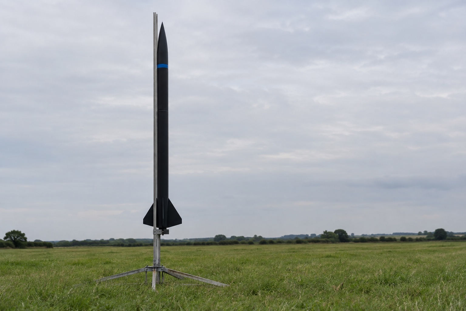
This is my build plan, not a record of a rocket I have already built or launched. High-power rockets should be flown through a recognised club under its Range Safety Officer. I am not making the motor or the deployment charge. I will use certified commercial hardware and follow the rules in force at the launch site.
I want to build a rocket.
Not one that goes to space. One that leaves the ground very quickly, goes higher than I can properly see, opens a parachute and comes back with a small memory card telling me what happened.
That last part is the actual project.
Making a tube go up is obviously difficult. But making it stable, getting it back in one piece and reconstructing the flight from noisy sensors is much more interesting.
So this is the plan.
Decide what a successful flight is#
It would be easy to define success as the rocket launched.
That is too easy. A rocket can launch, disappear, crash and still technically satisfy that sentence.
Mine has to do four things:
- Leave the rail and fly in a stable direction.
- Record useful acceleration, rotation and altitude data.
- Deploy its recovery system near the top of the flight.
- Return in a condition where I can fly it again.
If it goes high but the data logger fails, that is not a complete success. If the sensors work but the parachute does not open, that is definitely not a success.
The flight is a system. Every part has to finish its job.
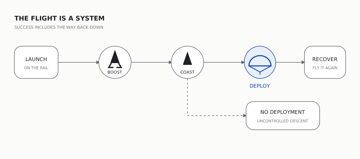
Diagram — the planned flight and the failure route I need to design against.
Start with the club, not the rocket#
My first instinct is to buy the most powerful motor I can use and work backwards.
That is the wrong order.
The first step is to find a recognised rocketry club, speak to its Range Safety Officer and understand the qualification route. In the UK, high-power flights sit within the UK Rocketry Association's certification and safety system. The person running the range has the final decision on whether anything flies.
This matters for an obvious reason: a badly built rocket is not just an unsuccessful project. It is a fast, heavy object whose landing point I no longer control.
So I need to learn with smaller flights first. Recovery packing. Rail setup. Wind. Stability checks. How motors are handled. What a safe launch day actually looks like.
The large rocket comes after that, not before it.
Draw the whole rocket before buying the parts#
A rocket looks simple from the outside. It is basically a tube with a point at one end and fins at the other.
Inside, it is a stack of jobs:
- The nose cone gives the front its shape.
- The payload bay carries the sensors, battery and logger.
- The recovery bay carries the parachute and harness.
- The body tube holds the structure together.
- The fins keep the rocket pointing into the airflow.
- The motor mount transfers thrust into the airframe.
- The rail guides hold the rocket straight until it is moving fast enough for the fins to work.
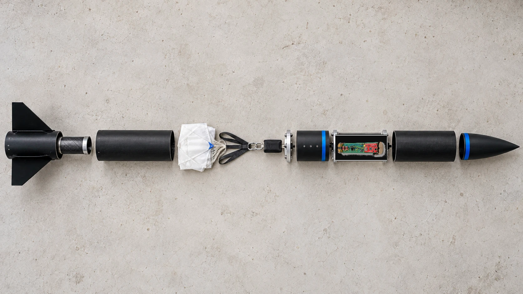
Illustration — the proposed airframe, recovery and avionics sections. It is not a photograph of a completed rocket.
The order matters because one decision moves everything else.
A heavier battery moves the centre of gravity. A larger payload bay makes the rocket longer. A different motor changes the thrust, total mass and expected altitude. A larger parachute reduces landing speed but takes more space and may drift further in the wind.
I cannot design each part alone and hope they become one rocket at the end.
Simulate it before cutting anything#
The first rocket should exist inside a simulator.
I can build the shape in OpenRocket or RockSim, then enter the parts, materials, masses and motor. The simulator estimates how the rocket accelerates, how high it may go and whether it has enough stability.
The important relationship is between the centre of gravity and centre of pressure.
The centre of gravity is where the rocket's mass balances. The centre of pressure is roughly where the aerodynamic forces act. For a passively stable rocket, the centre of gravity needs to sit ahead of the centre of pressure. UKRA's current safety code asks for at least one body diameter of separation.
Basically, the heavy balancing point should lead and the aerodynamic point should follow.
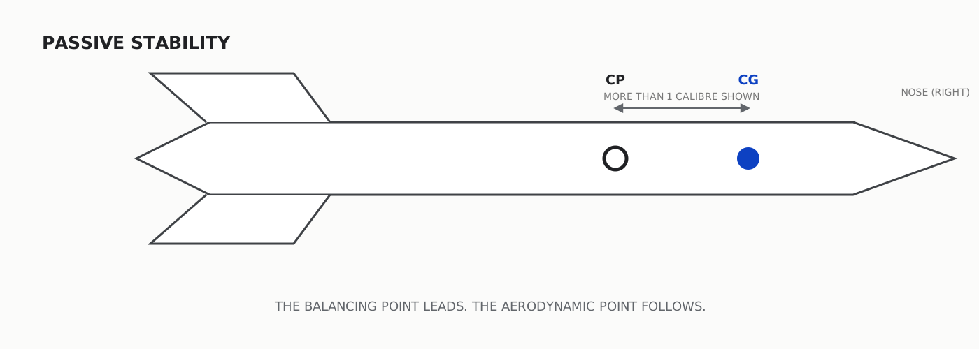
Diagram — the nose points right, so the centre of gravity leads the centre of pressure.
But a simulation is only as good as the numbers I give it.
So I will weigh the real nose cone, tube, fins, electronics, harness and parachute as I build them. Then I will update the model. I also need to simulate the exact commercial motor configuration, not a motor that looks close enough in a list.
The useful outputs are:
- rail-exit speed;
- maximum acceleration;
- stability margin;
- expected apogee;
- time to apogee;
- expected descent speed; and
- how far the rocket may drift under parachute.
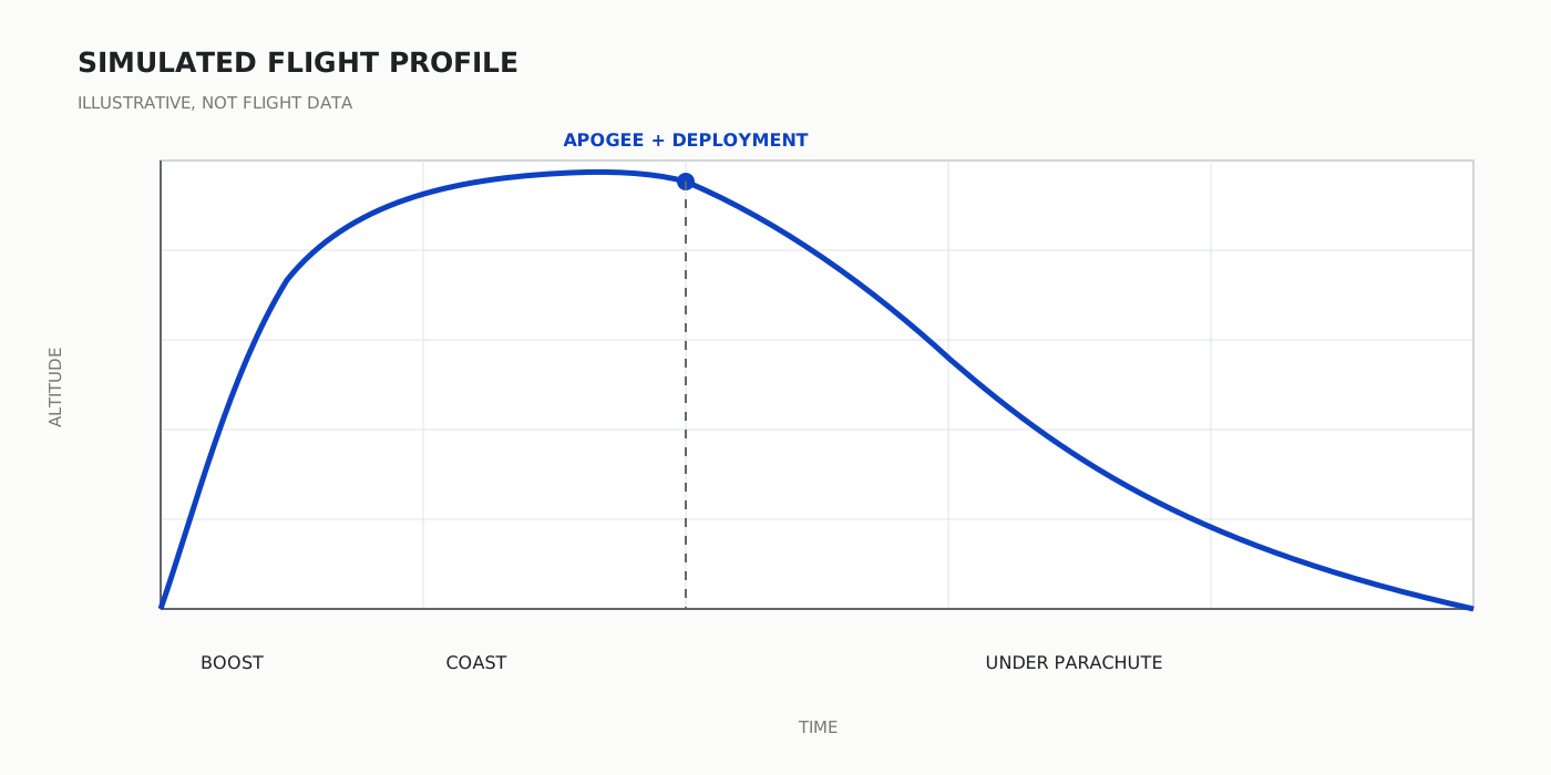
Diagram — an illustrative profile, not a simulated result for the finished rocket.
The graph is not a promise. It is a list of assumptions drawn as a line.
Build the airframe straight, strong and light#
There are three requirements here and they fight each other.
The rocket has to be strong enough to take the force of launch. It has to be straight enough to fly without introducing its own turn. And it has to be light enough that I am not wasting motor power lifting poor construction.
The build order is simple:
- Dry-fit the motor mount, centring rings and airframe.
- Make a jig so the fins are equally spaced and square to the body.
- Bond the internal parts using materials appropriate for the expected loads.
- Fit the rail guides on one straight line.
- Build attachment points for the recovery harness into the structure.
- Check that every section can still separate where it is meant to.
- Weigh everything again.
The finish will be black, with small blue marks for the centre of gravity, centre of pressure and separation points. The marks are not decoration. They make inspection easier.
And I will resist making the nose cone or fins from heavy metal simply because metal feels serious. The safest material is the one suitable for the loads, not the one that looks most like a missile.
The payload is the interesting part#
The rocket will carry a small flight recorder:
- a three-axis accelerometer;
- a three-axis gyroscope;
- a barometric pressure sensor;
- a microcontroller;
- a memory card;
- a battery; and
- a switch that can be reached while the rocket is on the rail.
The parts list is not enough. I also need to choose a measurement range that will not clip during launch, a sampling rate fast enough to see the interesting part of the flight, and connections that will survive vibration. Those requirements come before choosing the exact sensor boards.
The recorder will use one long green board between circular end plates, with the battery at one end and the data logger at the other. I am adding pressure measurement, but I do not need to make the layout more complicated than the job requires.
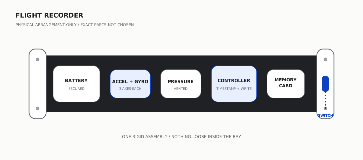
Illustration — the physical arrangement only. The exact boards and wiring come after the measurement range, sampling and vibration requirements are fixed.
The accelerometer measures acceleration along three axes. The gyroscope measures angular rate around those axes. The pressure sensor measures air pressure, which I can later turn into a second estimate of altitude. The microcontroller timestamps the readings and writes them to the card.
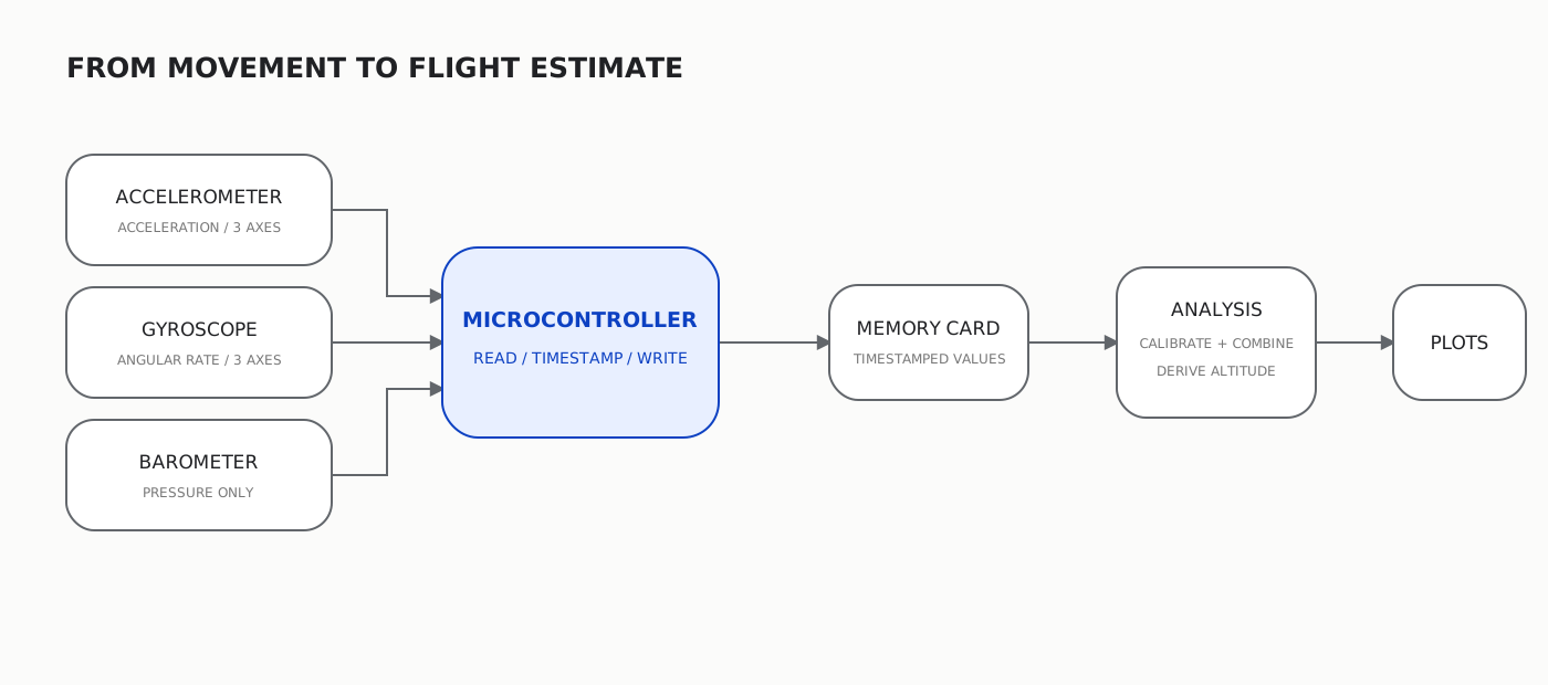
Diagram — altitude and the reconstructed path are calculated after the raw measurements have been recovered.
The logger should begin recording before launch and keep recording after landing. Storage is cheap. Missing the first half-second of flight is not.
I also need to mount it properly. If the circuit board can move inside the payload bay, the sensor records the board rattling as well as the rocket moving. That is technically data, but not useful data.
And the barometer needs to measure outside air pressure without sitting directly in turbulent airflow. That means a sealed electronics bay with correctly sized static-pressure ports, positioned away from rail buttons, joints and other things that disturb the air. The final port arrangement should follow the sensor manufacturer's guidance and be checked with the club.
Calibrate the sensors before trusting them#
A sensor produces numbers. That does not mean the numbers are true.
The accelerometer may report a small acceleration while sitting still. The gyroscope may report a small angular rate while nothing is moving. Integrate that error for long enough and the calculated orientation will slowly turn on paper. Two axes may even be labelled differently from the axes I drew for the rocket.
So calibration has to happen before the payload goes near a launch rail.
First, leave it still and measure the bias. Then rotate it through known positions and confirm which axis changes. After that, place it on a turntable or another controlled rotating platform and compare the measured rotation with the rotation I asked for. The payload has to be remounted for each axis. One flat spin does not test all three.
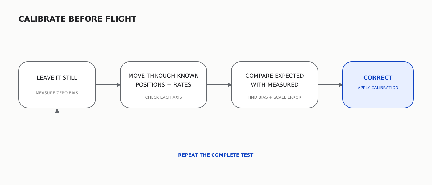
Diagram — repeat the controlled test after every correction.
I want to answer four questions:
- What does each axis actually point towards?
- What does the sensor read while stationary?
- Does the timestamp stay consistent while writing to the card?
- Does the battery last longer than the complete launch-day window?
This is boring compared with launching a rocket.
It is also how I find out whether the flight data will mean anything.
Make recovery part of the rocket#
The parachute is not an accessory added after the interesting engineering is finished.
It is the part that stops the rocket becoming a falling object.
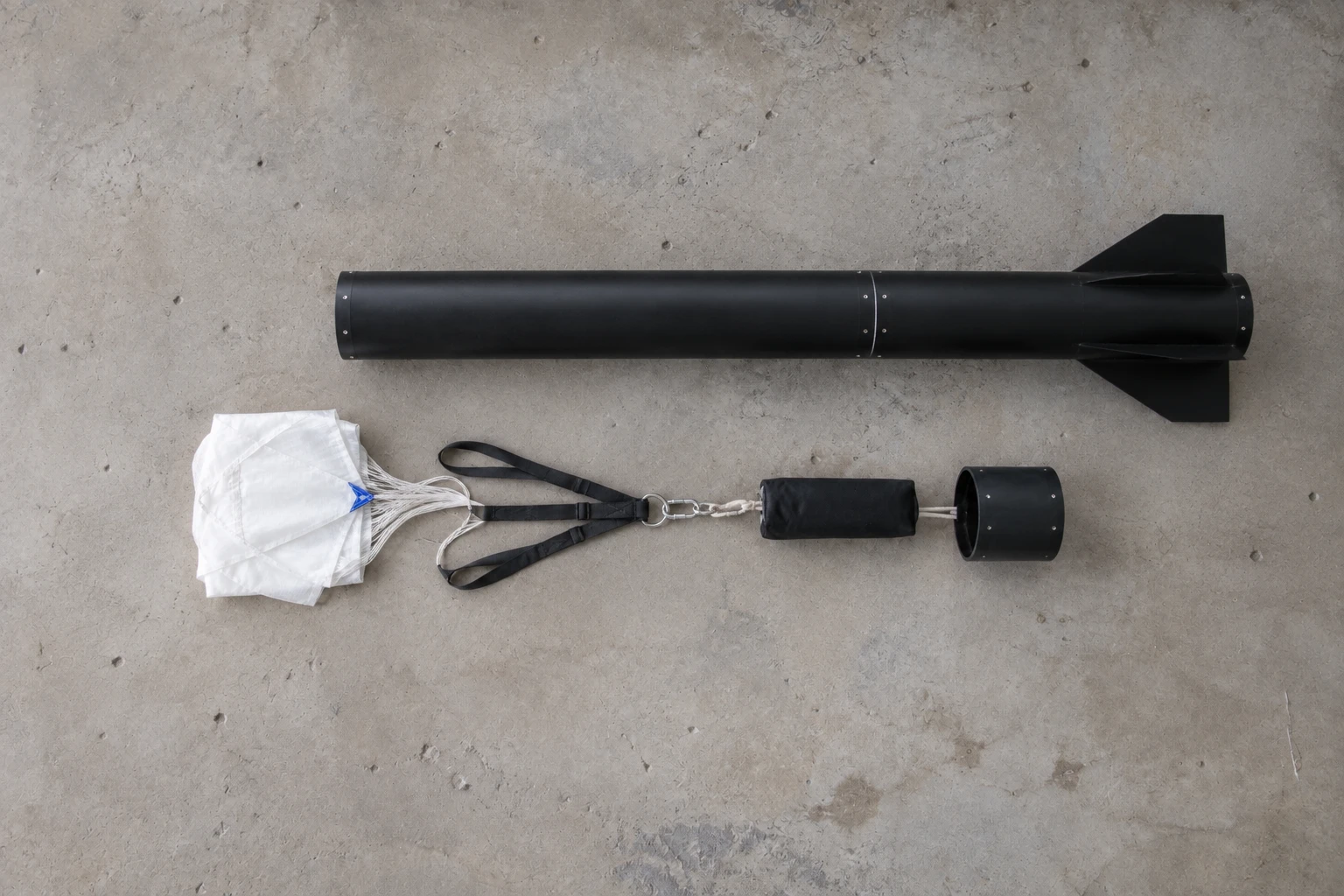
Illustration — the proposed recovery stack, shown outside the bay for clarity. The final hardware and packing method require club inspection.
The recovery system needs a strong harness, protected lines, a parachute suitable for the rocket's finished mass and a proven commercial deployment method. The exact installation and deployment setup should be agreed with the club and inspected by the Range Safety Officer. This is not where I invent my own pyrotechnics.
I need to test the non-pyrotechnic parts on the ground:
- Can the sections separate freely?
- Can the parachute leave the bay without snagging?
- Are the lines protected from heat and sharp edges?
- Is the harness attached to the structure rather than a weak cosmetic part?
- Is everything packed the same way each time?
An active recovery device is required for high-power certification flights. More importantly, it is required if I would like the rocket back.
Test the boring things together#
Individual parts working is not enough.
The complete rocket needs a rehearsal.
I will assemble it without a live motor and run the full sequence: power the logger, close the payload bay, leave it recording for longer than the expected wait and flight, open it again and check the file. Then repeat it.
After that:
- measure the final mass;
- find the real centre of gravity in the flight configuration;
- compare it with the simulation;
- check every fastener and attachment point;
- check that the rail guides move freely on the club's rail;
- confirm that the recovery section separates cleanly; and
- make a one-page launch checklist.
If the measured rocket and simulated rocket are now different, the simulation loses. Update it.
Launch day should feel slightly boring#
By launch day, most decisions should already be made.
The Range Safety Officer will inspect the rocket and can stop the flight. That is not a final obstacle to get around. It is the last independent check that the assumptions still match the object sitting on the pad.
The sequence is:
- Check the wind, field and expected drift with the club.
- Present the finished rocket, simulation and recovery plan for inspection.
- Prepare the certified motor and recovery hardware under qualified supervision.
- Fit the payload, start the logger and verify that it is recording.
- Put the rocket on the rail and complete the range checklist.
- Move to the safe distance.
- Launch only when the Range Safety Officer clears it.
I also want two cameras. One wide camera that never loses the launch rail, and another that follows the rocket. The video is not just for the nice bit where it leaves the ground. It gives me a second record to compare with the sensor data.
Turn the flight back into a model#
If the rocket returns and the memory card survives, I should have several columns of numbers:
time, ax, ay, az, gx, gy, gz, pressure
The first plots are straightforward: acceleration, angular velocity and pressure-derived altitude against time.
The next part is harder.
I can integrate angular rate to estimate orientation, rotate acceleration from the rocket's local coordinates into world coordinates, remove gravity, then integrate again to estimate velocity and position. But every integration also accumulates error. The result is an estimate, not a perfect replay of the flight.
That is why there is a barometer and video. I can combine them with the inertial measurements rather than trusting any one sensor on its own. The different records can disagree with each other in useful ways.
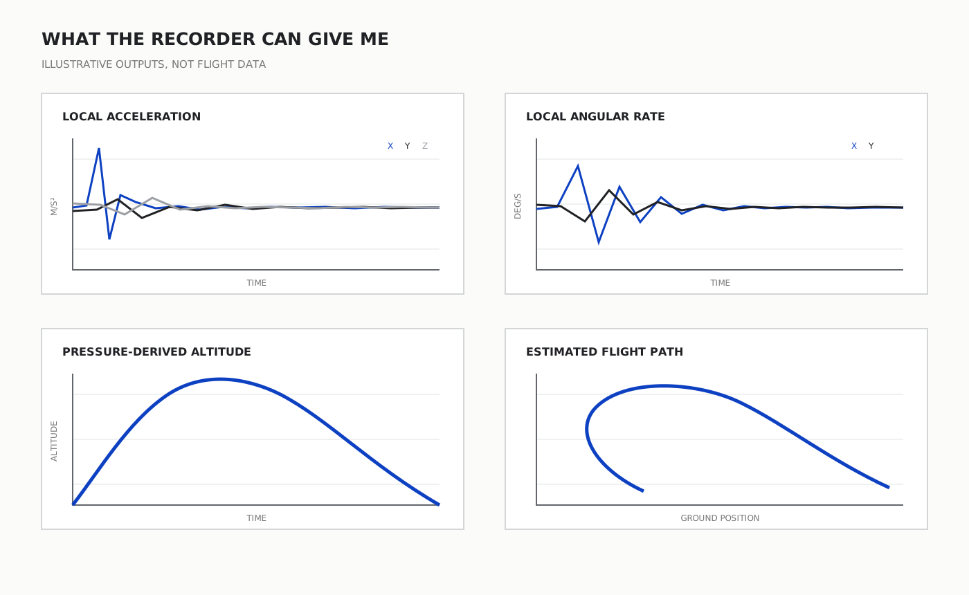
Charts — examples of the outputs I want, not presented as flight data. Reconstruction remains an estimate checked against independent observations.
The final comparison should have three layers:
- Simulation: what I thought the rocket would do.
- Sensors: what the payload calculated during the flight.
- Video and recovery point: what I can independently observe.
The gaps are the lesson.
Maybe the rocket is heavier than the model. Maybe the motor produced slightly different thrust. Maybe the wind turned it. Maybe the pressure sensor sat in turbulent air. Maybe the gyro bias made the calculated orientation slowly walk away from reality.
The job is not to make the plot agree with the simulation. It is to understand why it does not.
Then build the second rocket#
The first rocket will tell me what I forgot.
Perhaps the avionics bay is difficult to reach. Perhaps the black paint makes the rocket impossible to follow against trees. Perhaps the parachute bay is too small. Perhaps the sensor range clips at launch. Perhaps the memory card connector is not happy with vibration.
That is fine.
The first build turns the unknown problems into visible ones. The second build is where I can actually fix them.
The rocket is the obvious object in this project. But the thing I am really building is a loop:
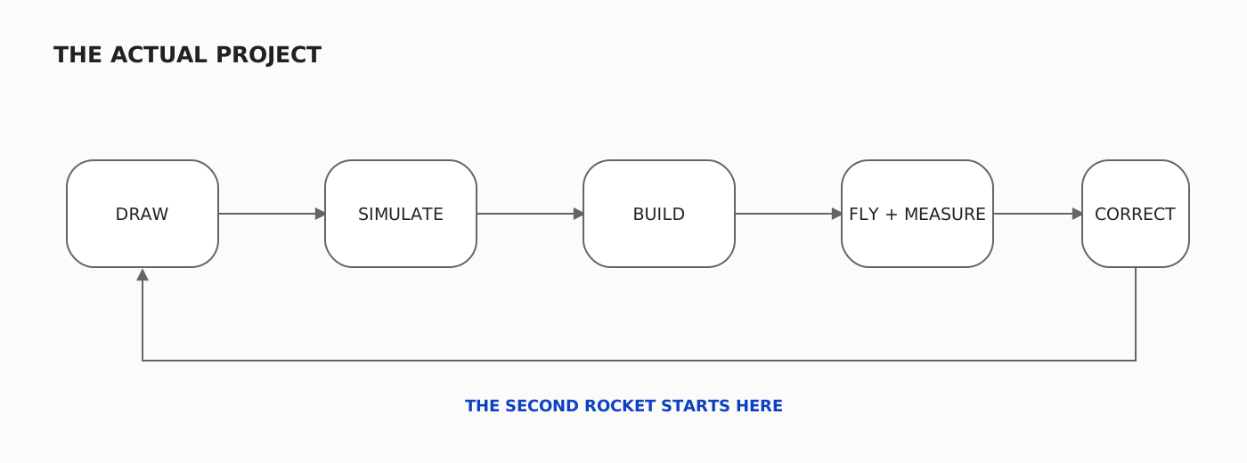
Diagram — the first flight exists to make the second design less wrong.
Draw it. Simulate it. Build it. Fly it. Measure what happened. Then correct the next one.
That is the project.
Research sources
- UK Rocketry Association, High Power Certification - current UK certification stages, stability knowledge, active recovery and successful-flight requirements.
- UK Rocketry Association, Safety Code - current construction, stability, launch-site and Range Safety Officer requirements. Safety rules change, so use the current code rather than treating a June 2013 note as authoritative.
- OpenRocket - open-source rocket design and flight simulation software.
- NASA Glenn Research Center, Model Rockets - the basic parts and forces of a model rocket.
- NASA Glenn Research Center, Rocket Stability - the relationship between centre of gravity and centre of pressure.
- Missile Works, RRC3 User Manual - practical guidance on sealed avionics bays and static-pressure ports for barometric altimeters.